40G Q/4SFP+ Direct Attach Cable JHA-QSFP-40G-PCU


General Description
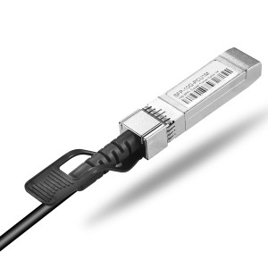
QSFP+ Direct Attach Cables are compliant with the SFF-8436 specifications. SFP+ Direct Attach Cables are compliant with the SFF-8431, SFF-8432 and SFF-8472 specifications. Various choices of wire gauge are available from 30 to 24 AWG with various choices of cable length(up to 7m).
Features
◊ Compliant with SFF- 8436, SFF-8431, SFF-8432 and SFF-8472
◊ Up to 10. 3125Gbps data rate per channel
◊ Up to 7m transmission
◊ Operating temperature: -40℃ to +80℃
◊ Single 3.3V power supply
◊ RoHS compliant
Benefits
◊ Cost-effective copper solution
◊ Lowest total system power solution
◊ Lowest total system EMI solution
◊ Optimized design for Signal Integrity
Applications
◊ 40G Ethernet
Specification
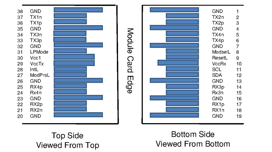
Pin Function Definition
QSFP+ Pin Function Definition
|
Pin |
Logic |
Symbol |
Description |
|
1 |
|
GND |
Ground |
|
2 |
CML-I |
Tx2n |
Transmitter Inverted Data Input |
|
3 |
CML-I |
Tx2p |
Transmitter Non-Inverted Data Input |
|
4 |
|
GND |
Ground |
|
5 |
CML-I |
Tx4n |
Transmitter Inverted Data Input |
|
6 |
CML-I |
Tx4p |
Transmitter Non-Inverted Data Input |
|
7 |
|
GND |
Ground |
|
8 |
LVTTL-I |
ModSelL |
Module Select |
|
9 |
LVTTL-I |
ResetL |
Module Reset |
|
10 |
|
Vcc Rx |
+3.3V Power Supply Receiver |
|
11 |
LVCMOS- I/O |
SCL |
2-wire serial interface clock |
|
12 |
LVCMOS- I/O |
SDA |
2-wire serial interface data |
|
13 |
|
GND |
Ground |
|
14 |
CML-O |
Rx3p |
Receiver Non-Inverted Data Output |
|
15 |
CML-O |
Rx3n |
Receiver Inverted Data Output |
|
16 |
|
GND |
Ground |
|
17 |
CML-O |
Rx1p |
Receiver Non-Inverted Data Output |
|
18 |
CML-O |
Rx1n |
Receiver Inverted Data Output |
|
19 |
|
GND |
Ground |
|
20 |
|
GND |
Ground |
|
21 |
CML-O |
Rx2n |
Receiver Inverted Data Output |
|
22 |
CML-O |
Rx2p |
Receiver Non-Inverted Data Output |
|
23 |
|
GND |
Ground |
|
24 |
CML-O |
Rx4n |
Receiver Inverted Data Output |
|
25 |
CML-O |
Rx4p |
Receiver Non-Inverted Data Output |
|
26 |
|
GND |
Ground |
|
27 |
LVTTL-O |
ModPrsL |
Module Present |
|
28 |
LVTTL-O |
IntL |
Interrupt |
|
29 |
|
Vcc Tx |
+3.3V Power supply transmitter |
|
30 |
|
Vcc1 |
+3.3V Power supply |
|
31 |
LVTTL-I |
LPMode |
Low Power Mode |
|
32 |
|
GND |
Ground |
|
33 |
CML-I |
Tx3p |
Transmitter Non-Inverted Data Input |
|
34 |
CML-I |
Tx3n |
Transmitter Inverted Data Input |
|
35 |
|
GND |
Ground |
|
36 |
CML-I |
Tx1p |
Transmitter Non-Inverted Data Input |
|
37 |
CML-I |
Tx1n |
Transmitter Inverted Data Input |
|
38 |
|
GND |
Ground |
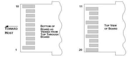
SFP+ Pin Function Definition
| Pin | Logic | Symbol |
Description |
|
1 |
VeeT | Module Transmitter Ground | |
|
2 |
LVTTL-O | Tx_Fault | Module Transmitter Fault |
|
3 |
LVTTL-I | Tx_Disable | Transmitter disable; Turns off transmitter laser output |
|
4 |
LVTTL-I/O | SDA | 2-wire Serial Interface Data Line (Same as MOD-DEF2 in INF-8074i) |
|
5 |
LVTTL-I/O |
SCL |
2-wire Serial Interface Clock (Same as MOD-DEF1 in INF-8074i) |
|
6 |
Mod_ABS | Module Absent, connected to VeeT or VeeR in the module | |
|
7 |
LVTTL-I |
RS0 |
Rate Select 0, optionally controls SFP+ module receiver |
|
8 |
LVTTL-O | Rx_LOS | Receiver Loss of Signal Indication (In FC designated as Rx_LOS and in Ethernet designated as Signal Detect) |
|
9 |
LVTTL-I |
RS1 |
Rate Select 1, optionally controls SFP+ module transmitter |
| 10 | VeeR | Module Receiver Ground | |
| 11 | VeeR | Module Receiver Ground | |
| 12 | CML-O |
RD- |
Receiver Inverted Data Output |
| 13 | CML-O |
RD+ |
Receiver Non-Inverted Data Output |
| 14 | VeeR | Module Receiver Ground | |
| 15 | VccR | Module Receiver 3.3 V Supply | |
| 16 | VccT | Module Transmitter 3.3 V Supply | |
| 17 | VeeT | Module Transmitter Ground | |
| 18 | CML-I |
TD+ |
Transmitter Non-Inverted Data Input |
| 19 | CML-I |
TD- |
Transmitter Inverted Data Input |
| 20 | VeeT | Module Transmitter Ground |
General Product Characteristics
| Q/4SFP+ DAC Specifications | |
| Number of Lanes | Tx & Rx |
| Channel Data Rate | 10.3125 Gbps |
| Operating Temperature | 0 to + 70°C |
| Storage Temperature | -40 to + 85°C |
| Supply Voltage | 3.3 V nominal |
| Electrical Interface | 38 pins edge connector(QSFP+)20 pins edge connector(SFP+)
|
| Management Interface | Serial, I2C |
High Speed Characteristics
| Parameter | Symbol | Min | Typ | Max | Units | Notes |
| Differential Impedance |
Zd |
90 |
100 | 110 |
Ω |
|
| Differential Input Return Loss |
SDDXX |
<-12+2* SQRT (f) with f in GHz |
dB |
0.01~4.1GHz | ||
|
<-6.3+13* Log10/(f/5.5) with f in GHz |
dB |
4.1~11.1GHz | ||||
| Common Mode Output Return Loss | SCCXX | < -7+1.6*f with f in GHz |
dB |
0.01~2.5GHz | ||
|
-3 |
dB |
2.5~11.1GHz | ||||
| Difference Waveform Distortion Penalty | dWDPc | 6.75 | dB | |||
| VMA Loss |
L |
4.4 | dB | |||
| VMA Loss to Crosstalk Ratio | VCR | 32.5 |
dB |
|||
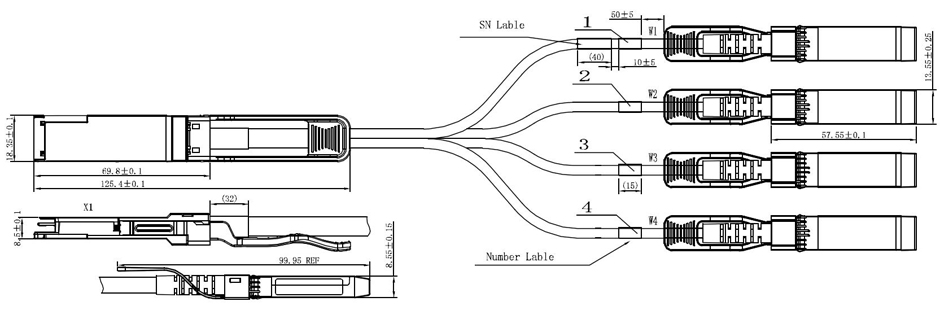
Mechanical Specifications
The connector is compatible with the SFF-8436 to SFF-8432 specification.
|
Length (m) |
able AWG |
|
1 |
30 |
|
3 |
30 |
|
5 |
26 |
|
7 |
26 |
Regulatory Compliance
|
Feature |
Test Method | Performance |
| Electrostatic Discharge (ESD) to the Electrical Pins | MIL-STD-883C Method 3015.7 | Class 1(>2000 Volts) |
| Electromagnetic Interference(EMI) | FCC Class B | Compliant with Standards |
| CENELEC EN55022 Class B | ||
| CISPR22 ITE Class B | ||
| RF Immunity(RFI) | IEC61000-4-3 | Typically Show no Measurable Effect from a 10V/m Field Swept from 80 to 1000MHz |
| RoHS Compliance | RoHS Directive 2011/65/EU and it’s Amendment Directives 6/6 | RoHS 6/6 compliant |