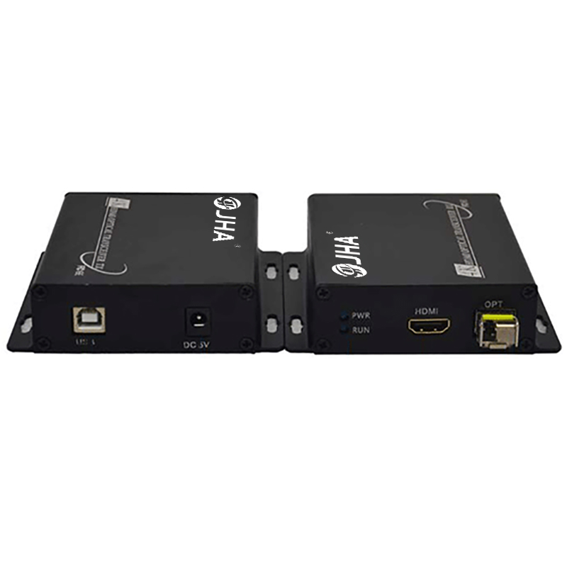
HDMI optical transceiver is a terminal device for optical signal transmission. In a wide range of applications, it is often necessary to transmit the HDMI signal source to a distance for processing. The most prominent problems are: color cast and blur of the signal received at a distance, ghosting and smearing of the signal, and screen interference. So, what are the common failure problems when we use HDMI video optical transceivers? 1. No video signal 1. Check whether the power supply of each device is normal. 2. Check whether the video indicator of the corresponding channel of the receiving end is lit. A: If the indicator light is on (the light is on, it means that the channel has video signal output at this time). Then check whether the video cable between the receiving end and the monitor or DVR and other terminal equipment is well connected, and whether the video interface connection is loose or has virtual welding. B: The video indicator light of the receiving end is not on, check whether the video indicator light of the corresponding channel at the front end is on. (It is recommended to re-power on the optical receiver to ensure the synchronization of the video signal) a: The light is on (the light is on means that the video signal collected by the camera has been sent to the front end of the optical transceiver), check whether the optical cable is connected, and whether the optical interface of the optical transceiver and the optical cable terminal box is loose. It is recommended to re-plug and unplug the optical fiber interface (if the pigtail head is too dirty, it is recommended to clean it with cotton alcohol and let it dry before inserting it). b : The light does not light up, check whether the camera works normally, and whether the video cable from the camera to the front-end transmitter is connected reliably. Whether the video interface is loose or has virtual welding. If the above methods cannot eliminate the fault and there are devices of the same type, the replacement inspection method can be used (equipment is required to be interchangeable), that is, the optical fiber is connected to the receiver that works normally at the other end or the remote transmitter can be replaced to accurately determine faulty equipment. Second, the screen interference 1. This situation is mostly caused by the excessive attenuation of the optical fiber link or the long front-end video cable and AC electromagnetic interference. a: Check whether the pigtail is excessively bent (especially during multi-mode transmission, try to stretch the pigtail and do not bend it excessively). b: Check whether the connection between the optical port and the flange of the terminal box is reliable and whether the flange core is damaged. c: Whether the optical port and pigtail are too dirty, use alcohol and cotton to clean them and then insert them after drying. d: When laying the line, the video transmission cable should try to use the 75-5 cable with good shielding and good transmission quality, and try to avoid the AC line and other objects that are easy to cause electromagnetic interference. 2. There is no control signal or the control signal is abnormal a: Check whether the data signal indicator of the optical transceiver is correct. b: Check whether the data cable is connected correctly and firmly according to the data port definition in the product manual. In particular, whether the positive and negative poles of the control line are reversed. c: Check whether the control data signal format sent by the control device (computer, keyboard or DVR, etc.) is consistent with the data format supported by the optical transceiver (for details of the data communication format, see the ** page of this manual), and whether the baud rate exceeds that of the optical transceiver. Supported range (0-100Kbps). d: Check whether the data cable is connected correctly and firmly against the definition of the data port in the product manual. In particular, whether the positive and negative poles of the control line are reversed. 
Post time: Aug-17-2022


